- All
- Product Name
- Product Keyword
- Product Model
- Product Summary
- Product Description
- Multi Field Search
 English
 English


Wire drawing is one of the most essential metalworking processes in modern manufacturing, playing a key role in producing high-quality wire used across multiple industries — from electrical engineering and automotive production to construction and telecommunications. In its simplest form, wire drawing is the process of pulling a metal rod or wire through a series of dies to reduce its diameter, increase its length, and improve its mechanical properties.
This deceptively simple process hides a remarkable degree of precision, engineering, and science. Wire drawing machines integrate advanced materials, lubricants, and automation systems to ensure consistent output, minimal waste, and enhanced wire performance.
In this comprehensive guide, we'll explore what wire drawing is, how it works, the equipment involved, types of wire drawing processes, advantages and challenges, and how modern trends — such as automation and sustainable manufacturing — are reshaping the field.
Wire drawing is a metalworking process used to reduce the diameter and increase the length of wire through mechanical deformation.
The process relies on drawing dies, lubricants, and tension control to achieve precise and smooth wire finishes.
Common materials used include copper, aluminum, steel, brass, and tungsten.
Modern wire drawing machines utilize automation, CNC systems, and real-time monitoring for higher productivity.
Factors such as die angle, reduction ratio, speed, and lubrication directly affect final wire quality.
At its core, wire drawing is a deformation process that transforms a thick wire rod into a thinner wire by pulling it through a sequence of dies. Each die has a slightly smaller diameter than the previous one, gradually reducing the wire's cross-sectional area.
The fundamental principle behind wire drawing is plastic deformation, where the material's shape changes permanently under tensile stress without fracturing. This process not only alters the geometry of the wire but also improves its tensile strength, surface finish, and dimensional accuracy.
When a wire rod is pulled through a die, the material undergoes a combination of compressive and tensile stresses. The die exerts compressive forces that squeeze the metal, while the pulling mechanism applies tensile forces to elongate it. The balance between these forces is critical — too much tension can cause the wire to snap, while too little pressure may lead to poor dimensional control.
Here's a simplified formula used in wire drawing analysis:

Where:
r = reduction of area
A1 = original cross-sectional area
A2 = final cross-sectional area
This reduction ratio determines how much deformation occurs in each pass.
The wire drawing process can be broken down into several key stages. Each stage contributes to producing consistent, high-quality wire.
| Step | Process Stage | Description |
|---|---|---|
| 1 | Preparation of Wire Rods | Cleaning and surface treatment to remove oxides, scale, and contaminants. |
| 2 | Annealing | Softening the metal to improve ductility and prevent cracking during drawing. |
| 3 | Lubrication | Applying drawing lubricants (soap, oil, or powder) to reduce friction and die wear. |
| 4 | Drawing | Pulling the wire through a series of dies to progressively reduce its diameter. |
| 5 | Intermediate Annealing (if required) | Re-annealing between stages to restore ductility in multi-stage drawing. |
| 6 | Finishing & Coiling | Final surface treatment, straightening, cutting, and coiling for delivery. |
Each step requires precision — even minor inconsistencies in die design, lubrication, or tension control can lead to wire breakage, rough surfaces, or inconsistent diameters.
Wire drawing is not a one-size-fits-all process. Depending on the wire material, intended application, and equipment, different types of wire drawing techniques are used.
In single wire drawing, one wire passes through a single series of dies. This method is typically used for high-precision or small-batch production.
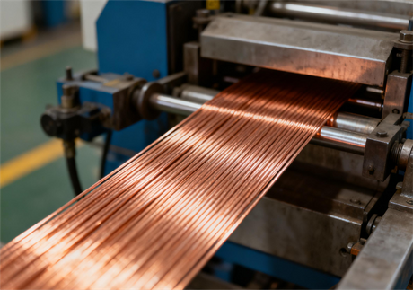
Multi-wire drawing uses multiple wires drawn simultaneously through a set of dies. It is efficient for mass production of small-diameter wires, especially for copper and aluminum conductors.
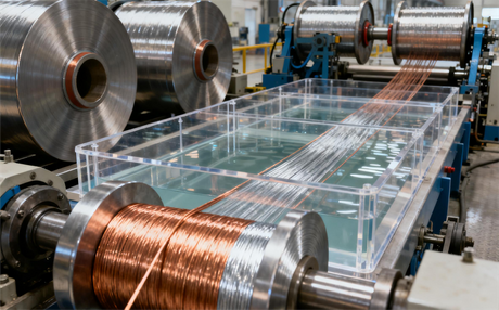
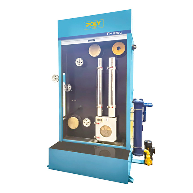
In wet wire drawing, both the wire and die are immersed in a lubricant bath during drawing. This helps reduce friction, cools the die, and produces a smoother finish.
In contrast, dry wire drawing applies solid lubricants like soap powder or lime before drawing. It is ideal for steel wire and hard materials.
Used for extremely small diameters (below 0.05 mm), fine wire drawing requires advanced machinery, precision dies, and controlled environments.
Although technically similar, tube drawing is used to reduce the diameter of hollow tubes rather than solid wires.
Wire drawing can be applied to a wide range of metals. Below are the most commonly used materials and their key characteristics.
| Material | Properties | Typical Applications |
|---|---|---|
| Copper | Excellent conductivity, ductility | Electrical wires, cables |
| Aluminum | Lightweight, corrosion-resistant | Power transmission lines |
| Steel (Carbon & Stainless) | High tensile strength, toughness | Springs, ropes, fasteners |
| Brass & Bronze | Corrosion-resistant, decorative | Musical instruments, connectors |
| Tungsten & Molybdenum | High melting point, strength | Filaments, precision components |
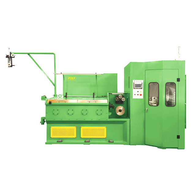
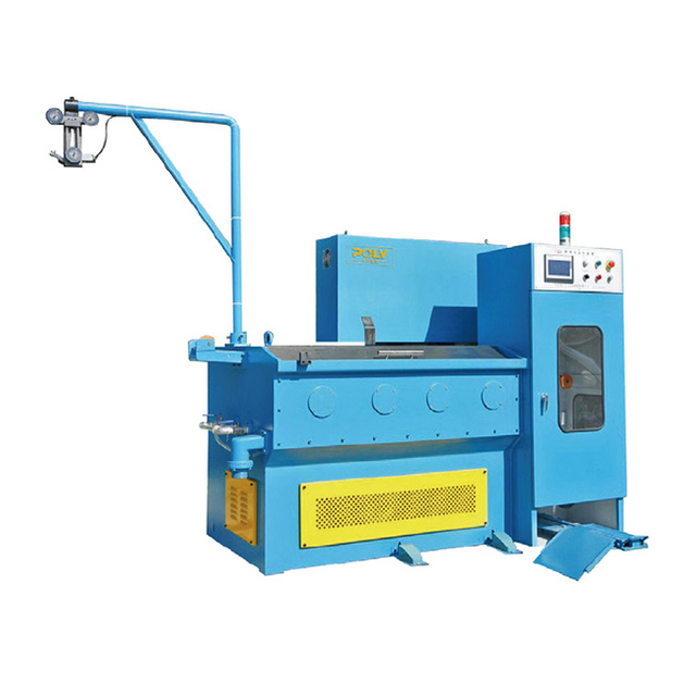
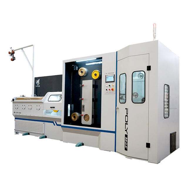
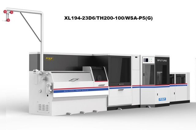
The wire drawing machine is the heart of the process. Modern systems use capstans or drums that pull the wire through dies under controlled tension. These machines may be mechanical, hydraulic, or servo-driven.
Drawing dies are precision tools made from tungsten carbide, diamond, or polycrystalline diamond (PCD). Die design — including die angle and bearing length — directly influences the wire's surface quality and lifespan.
Lubrication plays a crucial role in reducing friction, die wear, and heat generation. Systems vary from wet baths to spray lubrication systems.
After drawing, wires may undergo annealing to relieve internal stresses and improve flexibility.
Advanced laser micrometers and tension control systems ensure dimensional accuracy and uniform mechanical properties.
The quality and efficiency of wire drawing depend heavily on controlling several parameters:
| Parameter | Description | Optimal Effect |
|---|---|---|
| Die Angle | Determines deformation flow | Smaller angles for hard materials |
| Reduction Ratio | Amount of diameter reduction | Moderate ratio to avoid fractures |
| Drawing Speed | Affects friction and heat | Controlled speed ensures smoothness |
| Lubrication Type | Reduces friction | Wet or dry depending on material |
| Temperature | Influences ductility | Lower temperature avoids defects |
Maintaining the right balance of parameters leads to smoother surfaces, better dimensional control, and extended die life.
Wire drawing offers several engineering and economic benefits:
High dimensional accuracy and surface finish
Increased tensile strength due to work hardening
Material utilization with minimal waste
Scalability — from fine wires to heavy industrial cables
Adaptability for different metals and alloys
Cost efficiency compared to alternative forming methods
These advantages make wire drawing indispensable for manufacturing electrical components, automotive cables, and precision instruments.
Despite its advantages, wire drawing faces technical challenges that manufacturers must address.
Wire Breakage – Caused by excessive tension, poor lubrication, or improper die alignment.
Surface Defects – Scratches, scoring, or roughness due to die wear or impurities.
Residual Stresses – May lead to brittleness; requires annealing to relieve.
Die Failure – Wear and fracture of dies due to friction and heat.
Lubricant Contamination – Reduces process stability and surface finish.
In summary, wire drawing is far more than a basic shaping process — it's a highly engineered operation that blends material science, mechanical precision, and digital technology. By carefully controlling parameters like die geometry, speed, and lubrication, manufacturers can produce wires that meet stringent standards for strength, conductivity, and surface finish.
With sustainability, automation, and data-driven maintenance reshaping the field, wire drawing is poised to remain a cornerstone of industrial production for decades to come. Whether it's the copper strands in your smartphone or the high-tensile steel in a suspension bridge, the power of wire drawing continues to shape the world — quite literally.
Q1: What is the purpose of wire drawing?
A1: The main purpose of wire drawing is to reduce the diameter and increase the length of metal wire while improving its surface finish and mechanical strength.
Q2: What materials can be used in wire drawing?
A2: Common materials include copper, aluminum, steel, brass, and tungsten, depending on the end-use requirements.
Q3: What are drawing dies made of?
A3: Drawing dies are typically made from tungsten carbide, natural diamond, or polycrystalline diamond (PCD) for durability and precision.
Q4: Why is lubrication important in wire drawing?
A4: Proper lubrication minimizes friction, reduces heat, extends die life, and ensures a smooth wire surface.
Q5: What are common wire drawing defects?
A5: Defects include wire breakage, surface scoring, die marks, and residual stresses caused by improper process control.
Q6: How is wire drawing different from extrusion?
A6: In wire drawing, the metal is pulled through a die, whereas in extrusion, it is pushed through a die. Drawing provides better surface finish and dimensional control.


 簡(jiǎn)體中文